FAQ
CLASSIFICATION
>Attributes
TAXONOMY
FORMATION
Wall collapse
DIMENSIONS
Components
Terminology
>Synopsis
MEASUREMENT
Kolob Arch
Rainbow Bridge
Triangulation
Hopewell Arch
IDENTIFICATION
REFERENCES
The Dimensions of Kolob Arch
by Jay H. Wilbur
November, 2006 (revised January 2007)
SynopsisAlthough it is obvious that Kolob Arch is one of the largest natural arches in the world, its dimensions have not been known with much certainty prior to this paper. This was mainly caused by two circumstances. First, Kolob Arch is very challenging to measure. Physical access is limited and difficult. Second, until recently, no standard definitions were available to guide how the dimensions of a natural arch should be determined. As a result, all previous attempts to measure the arch produced inconsistent results and did not stand up to careful scrutiny. This lack of accurate measurements not only meant that the arch remained incompletely documented, it also prevented a proper comparison of Kolob Arch to the other great arches of the world. Fortunately, an accurate determination of the standard dimensions of the arch has now been accomplished. The results reported in this paper are:
- Span = 287.4 ± 2 feet
- Height = 104.7 ± 1 feet
- Width = 35 ± 3 feet
- Thickness = 75 ± 3 feet
- Separation = 44 ± 2 feet
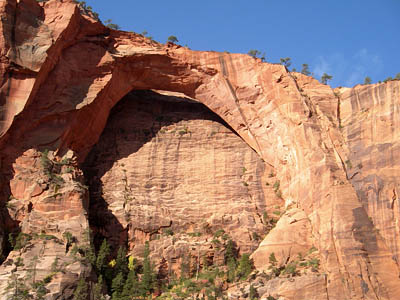
IntroductionKolob Arch in Zion National Park, Utah, is classified as an adult alcove natural arch within the standard taxonomy published by the Natural Arch and Bridge Society. Typical of alcove arches, it formed as a result of vertical joint expansion and wall collapse. Reference 1 describes in detail the standard taxonomy as well as these two processes of erosion. Acting together, they formed the arch on an exposed cliff of Navajo Sandstone in a remote part of the Park. The arch is located at UTM coordinates 12S-309018E-4143957N (WGS84). A photograph is provided in Figure 1.
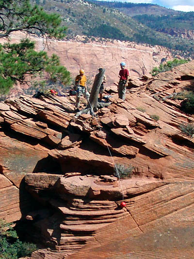
Figure 1 (photo by Craig Shelley)As is evident from the photo, Kolob Arch is quite large, with a massive lintel supported by massive abutments attached to the cliffwall. Despite the impression of strength and stability it creates in the minds of many observers, the arch is actually rather fragile. Both abutments are only weakly attached to the cliffwall along the same joint that allowed the arch to form in the first place. Indeed, were it not for two unusual features of the arch, it likely would have sloughed off the cliff long ago.
Kolob Arch is roughly aligned along a north-south axis. Figure 1 was taken with the camera pointing west. The abutment on the right side of the photo is referred to as the north abutment. The one on the left is called the south abutment. The cliff behind the arch takes a sharp turn to the east just north of where the north abutment attaches. The south abutment is much higher than the north abutment. Because of this configuration, the inverted catenary shape of the arch diverts its weight horizontally into the massive cliff of rock just north of the arch. This significantly reduces the vertical component of the weight that must be supported by the attachment of the abutments to the cliffwall.
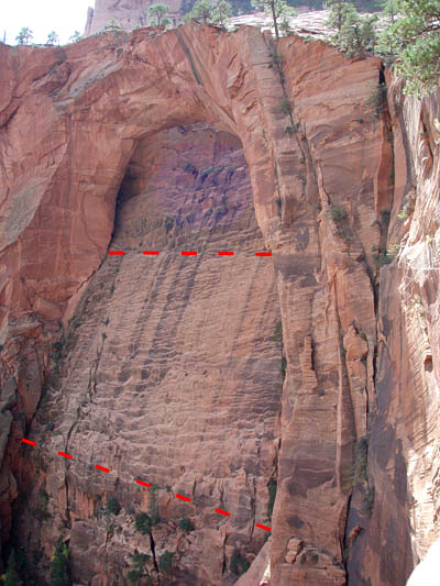
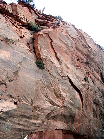
Figure 2 is a photo of the arch from atop the cliff where it curves eastward. This perspective shows that the cliffwall behind the arch does not have a constant slope. Rather, it is somewhat less steep directly under the arch. This reduction in slope provides additional support against the vertical component of the arch's weight. The fact that the east-west width of the abutments corresponds to the width of this "ledge" (indicated by dashed lines in Figure 2) is no coincidence. It enabled the arch to form in the first place.
Figure 2 (photo by Wade Christensen)These two features of Kolob Arch, the redistribution of much of its weight horizontally into the cliff to the north and the support lent to it by the "ledge", are also responsible for another important characteristic of the arch — its size. Together, they permit the arch to be one of the largest in the world.
Of course, erosion never ceases. The widening of the joint between the abutments and the cliffwall is proceeding rapidly. In the very near geological future, perhaps even within the next few hundred years, the vertical component of the weight of the south abutment will no longer have sufficient support. At that point, gravity will reduce the arch to rubble. What took millennia to form and develop will be destroyed in seconds.
Although local ranchers knew about Kolob Arch as early as the late 19th century, it was not widely publicized until a January, 1954, National Geographic article about Zion National Park included a photo and brief description of it. Three years later it was officially named Kolob Arch. In the Mormon faith, Kolob is the name of the greatest of all the planets in the universe and is closest to God's Throne. Naming the arch after Kolob was believed appropriate for two reasons. First, it is at the center of some of the most majestic scenery on Earth. Second, it was already considered to be the largest natural arch in the world by the Park and local residents.
This belief was based on a report filed with the Park by Fred D. Ayres and A. E. Creswell (Reference 3). Ayres and Creswell climbed to the top of the arch on August 12, 1953, the first successful ascent. They repeated this feat on August 14, and took rough measurements of the arch's dimensions. Their results included an estimate that the arch's span was between 290 and 310 feet. Their report compared this result to Landscape Arch and Rainbow Bridge. They quoted the span of Landscape Arch as 291 feet and the span of Rainbow Bridge as 287 feet, without listing sources.
Some thirty years later, two separate teams sponsored by Brigham Young University (BYU) made measurements of the arch from below. The first team, led by Reed Blake in 1983, reported a span of 310 feet (Reference 4). In 1984, the team led by Dale Stevens reported a span of 292 feet (Reference 5). Despite being sponsored by a major university, with faculty members as the two principal investigators, neither of these efforts resulted in a refereed paper published in a professional journal. The difference in their results led to a heated controversy, primarily because of Stevens' concurrent measurements of Landscape Arch in Arches National Park, and his claim that it was larger than Kolob Arch.
Stevens' measurement of Landscape Arch was also done under BYU sponsorship (Reference 6). Actually, Stevens did not take a measurement of the span of that arch. Rather, one of his measurements, the "horizontal line width", was mistakenly assumed to be a span measurement. His value of 301 feet was at variance with the previously accepted value of 291 feet obtained by Arches National Park staff and others, but it supported his claim that Landscape Arch was larger than Kolob Arch. Some people even quoted his value of 306 feet for the "light at widest place" as the span of Landscape Arch.
In 1992, the author of this paper attempted to measure Kolob Arch from below. He obtained a result for the span of about 294 feet with an error bar of plus or minus 12 feet. Unfortunately, none of these previous measurements, Ayres/Creswell (1953), Blake (1983), Stevens (1984), and Wilbur (1992), were done with sufficient rigor and precision to warrant much confidence in the correctness of the reported results. The best that could be safely concluded from a review and comparison of these four efforts was that the span of Kolob Arch was somewhere between 282 and 306 feet. This left plenty of room for disagreement over which of these two giants, Landscape Arch and Kolob Arch, was, in fact, the largest.
In 2004, the author requested and received permission from Arches National Park to re-measure Landscape Arch using the standardized definitions developed by the Natural Arch and Bridge Society. These definitions are also found in Reference 1. Applying modern laser ranging technology, the author confirmed the older value for the span of Landscape Arch with a high degree of precision, obtaining a value of 290 feet, with an error bar of less than one foot. This result, coupled with the four measurements of Kolob Arch described above, cast serious doubt on the claim by Stevens that Landscape Arch was larger than Kolob Arch. Reference 2 provides details about the author's measurement of Landscape Arch.
Thus, when the author led a team to Kolob Arch in October, 2006, to obtain measurements of comparable precision to those obtained at Landscape Arch two years earlier, it was with the full expectation that the results would finally confirm that Kolob Arch had the greater span. These expectations were not realized. The span of Landscape Arch is about 3 feet greater than the span of Kolob Arch. The remainder of this paper presents the measurements obtained by the author's team, discusses their accuracy and precision, and compares them to the results of the four previous measurement efforts listed above.
MethodologyKolob Arch is very difficult to access. Its location is isolated from the surrounding terrain by sheer, massive cliffs in every direction. Since the area is managed as wilderness, motorized vehicles are prohibited. Consequently, any equipment used must be packed or hiked in seven miles, and then carried up to the arch via a difficult technical climb. Even then there are problems with access. The top of the lintel is accessible after the climb, but other key points are not. For example, the baseline of the arch cannot be reached except via rope. The measurement equipment selected for use in these circumstances must be small, light-weight, and, of course, accurate.
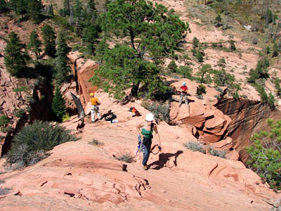
On October 3, 2006, Wade Christensen, Josh Heiner, Tim Nguyen, Craig Shelley, James Vlahos, Dawn Kish, and Tom Grundy successfully climbed to the top of Kolob Arch. This was only the fifth documented ascent that succeeded in reaching the lintel of the arch. This team, sponsored in part by the Natural Arch and Bridge Society and National Geographic Adventure Magazine, carried with them measurement equipment, photographic equipment, and a plan for measuring the arch. The author remained at an observation point below the arch and, in coordination with the team on, around, and under the lintel, successfully measured the standard dimensions of the arch. Multiple, independent methods were used to measure the arch's span. The planning for this effort, done principally by Shelley and the author, was aided by data supplied by the staff of Zion National Park, especially Dave Sharrow. Their assistance is gratefully acknowledged.
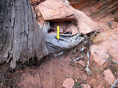
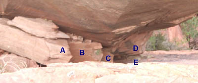
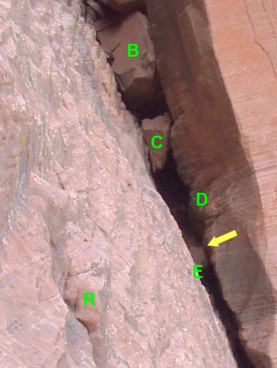
The width, thickness, and height of the arch were measured using a tetherball attached to a one-eighth inch braided nylon line. First, the narrowest part (horizontally) of the lintel was located visually. Next, a mark made on a stump on top of the lintel at this narrowest part was selected as a reference point. Figure 3 provides a photo. Finally, the tetherball was extended or lowered to appropriate points and the line was used to measure the distance to those points from the reference point. Subsequent calculations produced the width, thickness and height of the arch.
Figure 3 (photo by Craig Shelley)A cross-section of the lintel at its narrowest is approximated by the schematic in Figure 4. The reference point is labeled R in this drawing. Except for the inside, top corner of this cross-section, it is essentially rectangular. This "missing" corner made it impossible to extend the tetherball to or from point B. Instead, the distances between points A and R, R and C, and R and D were measured directly and then used to calculate the distances between A and B (the width) and between B and D (the thickness). Figures 5, 6, and 7, show the placement of the tetherball at points A, C, and D respectively.
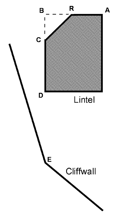
Figure 4
Figure 5 (photo by Wade Christensen)
Figure 6 (photo by Wade Christensen)
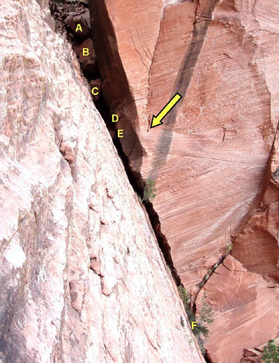
Figure 7 (photo by Wade Christensen)The tetherball was then extended downward vertically until it made contact directly below with the cliffwall at point E (not shown to scale in Figure 4). The line was then used to measure the distance between D and E (the height). The dimensions of the tetherball, an eight-inch diameter sphere, were included where appropriate in these measurements and calculations.
The endpoints of the opening breadth, used to determine the span of the arch, were found visually from below, above, and from vantage points near point E on the cliffwall. These vantage points were reached by free rappels off of the lintel. These were the first documented free rappels off of Kolob Arch. During one of these rappels, the minimum distance between point D and the cliffwall (the separation) was measured directly using a Leica laser range finder.
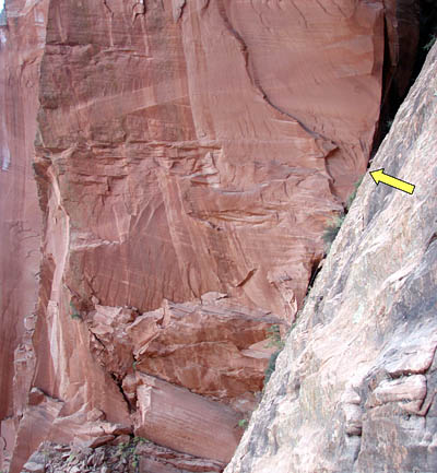
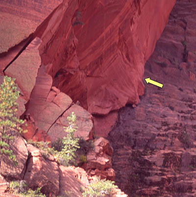
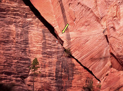
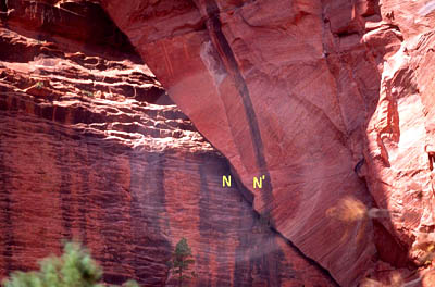
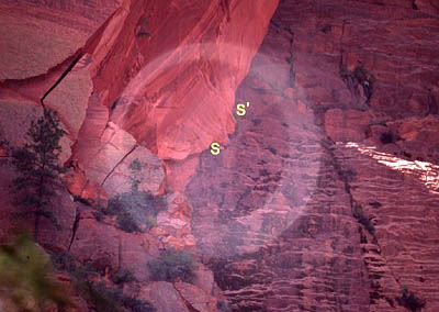
The arrows in Figures 8 and 9 show the locations of the south and north endpoints respectively. Figure 10 is a detail of the side view of the north endpoint. Again, the arrow indicates the north endpoint. The letters in Figures 9 and 10 identify common points of reference used to properly locate the north endpoint.
Figure 8a - The south endpoint seen from the side
(photo by Wade Christensen)
Figure 8b - The south endpoint seen from the front
(photo by Jay Wilbur)
Figure 9a - The north endpoint seen from above
(photo by Wade Christensen)
Figure 9b - The north endpoint seen from the side
(photo by Wade Christensen)
Figure 9c - The north endpoint seen from the front
(photo by Jay Wilbur)
Figure 10 - detail of the side view of the north endpoint
(photo by Wade Christensen)Attempts to place the tetherball at these two opening breadth endpoints were not successful because of the lintel's irregular surface and chock stones in the crevices between the cliffwall and abutments. However, the tetherball was positioned close enough to the south endpoint to determine the vertical distance between it and the top of the lintel directly above it. This value was then used with the values for the arch's height and thickness to roughly estimate the slope of the top of the lintel from south to north.
Three independent methods were used to determine the opening breadth and the span of the arch. For ease of reference, these are called the photo method, the angle method, and the scale method. Each of these methods is now described in turn.
The photo method involved measuring and analyzing photographs of the arch taken from vantage points at and near the observation area below the arch. Photographs were taken using calibrated Nikon lenses with 50mm and 100mm focal lengths. A three-dimensional grid was established at the observation area so that the camera locations of all photographs could be precisely located relative to each other. Distances between camera locations were measured using a Leica laser range finder. Distances between camera locations and key points on the arch and cliffwall behind it were measured using a Nikon laser range finder. Elevation angles for each photograph were measured using a Johnson angle locator. The resulting 35mm film images were digitally scanned into a computer and measured with Microsoft image measuring software.
The Nikon laser range measurements were used to determine the distances from camera locations to the arch and also the vertical and horizontal skew of each image plane relative to an imaginary reference plane at the arch. This reference plane is a vertical plane intersecting the baseline of the arch (the higher dashed line in Figure 2). In addition to the baseline, the reference plane includes the back, inside face of the lintel (roughly), the vertical line between points D and E (the height), and the opening breadth and span of the arch. However, since photographic images are projected onto a plane (the image plane) that is perpendicular to the line-of-sight, all images taken from the observation area were skewed at angles from the reference plane both vertically and horizontally. These skew angles must be, and were, accounted for in analyzing the images. The horizontal skew was determined by a series of laser range measurements to points along the baseline. This angle was confirmed to within half of a degree by examination of aerial photography. The vertical skew was determined by range measurements to points D and E, as well as by directly measuring the line-of-sight elevation angle of each photograph with the Johnson angle locator. The elevation angles of photos taken at the origin of the grid were also confirmed using measurements taken as part of the angle method.
Each image taken as part of this method was measured and analyzed to determine the length of the opening breadth. Because multiple images were taken with lenses of different focal length and at different locations in the grid, lens focal length and image scanning and processing were eliminated as sources of error in the results. By far, the largest remaining source of potential error in these results is the laser range measurements between camera locations and the arch. However, it should be noted that the horizontal skew measurement was not significantly biased by this since any bias in the ranger was the same for all range measurements taken in this series. This leaves the raw distance between camera and reference plane as the primary potential source of error for this method. Calibrations done on the Nikon laser range finder, both before and after, were used to estimate this error.
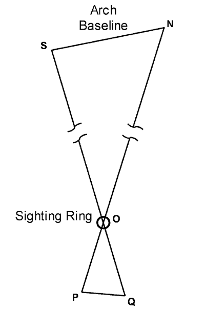
The angle method involved determining the angle subtended by the opening breadth at a specific point at the observation area. This point was the origin of the 3-D grid established in the photo method.
First, a sighting loop was positioned at the origin. Next, camera positions were found such that each endpoint of the opening breadth could be seen centered in the sighting loop using a 500mm Nikon reflecting telescopic lens. This configuration is depicted schematically and not to scale in Figure 11. Points S and N are respectively the south and north endpoints of the opening breadth. Point O is the origin of the grid and the location of the sighting loop. The specific locations of points P and Q in the 3-D grid (the two camera positions) were chosen so that points P, O, and N were co-linear and points Q, O, and S were also co-linear. This means that all five points were co-planar and that angle POQ was identical to angle SON, the angle we want to find.
Figure 11Next, the distances between points P and O, Q and O, and P and Q were very precisely measured. Using trigonometry (law of cosines), the angle POQ was calculated from the lengths of the three sides of this triangle. The distance between points S and N was then calculated, again using trigonometry, by combining the included-angle (SON, which is identical to angle POQ) with the distances between points O and S, and O and N, both determined by laser ranging. Finally, the exact locations of points P, Q, and O in the 3-D grid were used to independently compute elevation angles for the photos taken from point O as part of the photo method.
As it turned out, the points centered in the sighting loop by this method, points S and N in Figure 11, were not exactly the correct endpoints of the opening breadth. Figures 12 and 13 are the images taken through the sighting loop from points P and Q. The loop is blurred in each photo because the lens is focused on the arch. Thus, the distance between S and N had to be corrected by offsets at both endpoints in order to arrive at the distance between S' and N', the true endpoints of the opening breadth. These offsets were computed using photo analysis of the 500mm images.
Figure 12 (photo by Jay Wilbur)
Figure 13 (photo by Jay Wilbur)Note that the angle method is independent of any skew between the line-of-sight and the orientation of the arch. Trigonometry allows direct computation of the length of the opening breadth regardless of the angle of perspective. The primary source of error in this method was the measurement of the distance between points P and Q. A one sixteenth-inch error in this measurement translated into an error of one and a half feet in the calculation of the opening breadth. By comparison, it would require an error of 15 feet in the range measurements of distances OS and ON to cause the same amount of error in the calculation of the opening breadth. The range measurements obtained were about an order of magnitude better than that.
The scale method involved using the tetherball/line measurement of the distance between points D and E in Figure 4 (the height) to determine the scale of a photo taken from the origin of the grid established as part of the photo method. Regardless of how accurately DE represents the height of the arch (this is discussed further in the Results section below), that distance was very precisely determined to within a few inches. Thus, it determined the scale of photos taken from the observation area with the same precision. Measuring the opening breadth using this distance as the scale still depends upon accounting for the vertical and horizontal skew of the image plane from the reference plane (described in the photo method above), but is otherwise independent of range measurements and lens focal lengths. Again, both of these skew angles were very precisely determined. Hence, this method was a more direct and precise way to determine the opening breadth than the other two methods employed.
It should be emphasized that these three methods of determining the opening breadth were truly independent of each other. The biases and primary sources of random error were different for each. This means that if any significant error were made in the measurements or calculations of any one method, the results of that method would be significantly different from the other two. The fact that all three methods produced results that agree closely with each other is strong evidence in support of the correctness of these results.
Finally, to compute the span for the arch, the opening breadth must be projected onto the horizontal. Using the range measurement series along the baseline and the elevation measurements for each, the tilt between the opening breadth and the horizontal was calculated to be less than half a degree. Furthermore, the expected error for this computation was also about half a degree. Thus, our method did not reliably determine any tilt at all. Hence, it was assumed that for Kolob Arch the span equals the opening breadth. If there were a small tilt, it would mean that the span is a few inches less than reported here but still within the estimated error bars.
ResultsUsing the methods describe above, the author determined the following dimensions for Kolob Arch:
- Span = 287.4 ± 2 feet
- Height = 104.7 ± 1 feet
- Width = 35 ± 3 feet
- Thickness = 75 ± 3 feet
- Separation = 44 ± 2 feet
The three methods used to determine the span produced these results:
- Photo method = 286.7 ± 3 feet
- Angle method = 286.3 ± 3 feet
- Scale method = 288.2 ± 2 feet
The reported span is the weighted average of these three results. The result from the scale method was weighted twice that of the other two methods because of its greater precision. An unweighted average would be slightly smaller.
The height reported above must be qualified by the following consideration. The height measurement was taken at only one place along the lintel. This place is where the lintel is narrowest horizontally. It was assumed that this is also where the lintel is narrowest vertically. Such may not be exactly the case. If the height measurement was taken at the wrong place on the lintel, then the reported height would be underestimated. Also, the reported thickness would be commensurately overestimated. However, an examination of photographs showed that the amount of bias that might have entered the reported results from this possible source could not be more than two feet and is probably less than a foot. This is less than the reported error for the thickness and hence that result does not need to be qualified. On the other hand, the reported error for the height does not accommodate this possible bias. To accommodate it, the height measurement should be reported as between 104 and 107 feet with a best estimate of 105 feet. It is reported as it is above to emphasize the precision obtained on the measurement itself. Regardless of how accurately this measurement reflects the height, this was the precision obtained. This is important for estimating the precision obtained in the scale method used to determine the span.
Two other results are reported here. First, the vertical distance from the south span endpoint to the top of the lintel directly above it was found to be 239 feet. Thus, the top of the lintel slopes downward from south to north at an angle of roughly 25º. These two results are useful in comparing our results to those reported by Ayres and Creswell.
Discussion and ConclusionsOf all the previously reported measurements of Kolob Arch, those of Ayres and Creswell (1953) are the best documented as to what was measured and how it was measured. Furthermore, much of the Ayres and Creswell data was obtained using methods apparently similar to those used by the author's team. It is very instructive to compare their data to ours. We start with a comparison of lintel measurements.
Our measurement of the lintel's thickness is 75 feet. This measurement was obtained where the width of the lintel is at its minimum. Suspending a rock on a line, a method very similar to ours, Ayres and Creswell reported a "vertical thickness, measured at the back" of 80 feet. However, they took their measurement "near the center" of the arch. It is likely they took their measurement at a different place than we did and got a somewhat larger value. Our value is preferred because it more closely conforms to the standard definition of the lintel's thickness.
Our measurement of the lintel's width is 35 feet, taken in accordance with the standard where this value is at its minimum. The standard also calls for a horizontal measurement. Remember that we had to calculate this by combining two measurements, one horizontal and one at a slope. The language Ayres and Creswell use to describe their measurement of "the transverse width at center" is interesting. The report reads, "the transverse distance across the top surface of the bridge varies somewhat. We made a measurement over the center of the arch." This language suggests that their measurement of 65 feet, almost twice our value, was neither horizontal nor the minimum width. They probably stretched the line over the rounded, convex, top surface of the lintel at some representative width and reported the length of the line without compensating for the large deviation from a straight, horizontal line that would result.
Again using a method very similar to ours, Ayres and Creswell reported a measurement of the arch's "height to top surface, measured at back" of 240 feet. This number is substantially at odds with the sum of the height and thickness we obtained, 180 feet. Interestingly however, their number is almost exactly what we obtained as the vertical distance between the south endpoint and the top of the lintel at the back. The top of the lintel is at its highest at this south end. Without the benefit of a standard definition of an arch's height, it would have been very natural for them to take a "height" measurement at this highest point. Again, our measurements conform to the standard definitions.
Finally, we examine their "span" measurement. In this case, their method was quite different from any we used. First, they visually determined the endpoints of the opening and marked corresponding points on top of the lintel. Next, they measured the distance between these two points along the length of the lintel. Finally, they projected this result onto the horizontal using a slope for the top of the lintel which they estimated to be 20º. They reported their value for the span as "about 290 - 310 feet". This result could also be written as 300 feet, plus or minus 10 feet. As stated above, we measured the slope of the lintel's top surface from south down to north as about 25º. If one corrects their result for a horizontal projection of 25º rather than 20º, their result becomes 289 feet, plus or minus 10 feet, a result quite consistent with what we report above.
Next, we compare our results to the other previous measurements, beginning with the author's own attempt in 1992. With the benefit of a much closer examination of the arch, the author now realizes that two significant errors were made in his earlier attempt. First, the north endpoint was incorrectly placed in that earlier attempt. That is not too surprising since the correct endpoint is obscured by a flange of rock for observers positioned below the arch. Undoubtedly, the attempts by Blake and Stevens also suffered from this. Second, the author's earlier attempt was flawed by an inaccurate estimate of the line-of-sight distance between the camera and the arch.
In 1984, Stevens used a method somewhat similar to our scale method to measure the opening breadth of the arch. As stated above, the opening breadth for Kolob Arch is essentially identical to the span. Hence, the confusion about his measurement of Landscape Arch is avoided for Kolob Arch. He reported 292 feet, but did not discuss what precision he obtained. We believe it was similar to what Ayres and Creswell achieved in 1953, and what the author got in 1992, i.e., plus or minus about 10 or 12 feet. If this is accepted, the Stevens result is also consistent with what we report for the span.
The value Blake reported in Reference 4 for the span of Kolob Arch, 310 feet, is in clear disagreement with our results. Fortunately, although Blake's paper presents very little information about how his measurements were taken, the field notes of his survey team are preserved in the Park's library, attached to their copy of the Blake paper. Blake's survey team was led by Clyde Naylor. Their notes, Reference 7, were taken and signed by one of the members of the team, James Williams. Not only do these field notes point to how Blake came to overestimate the span of Kolob Arch, they provide very accurate data that can be used to confirm, almost exactly, our result of 287 feet for the span. This analysis is presented in the Appendix.
Finally, we address whether or not our results warrant designating Landscape Arch as the largest arch in the world so far documented. Readers may note that the author's result for the span of Landscape Arch was 290 ± 1 feet, and his result for the span of Kolob Arch was 287 ± 2 feet. Is it not possible then that they are tied for first with a common value of 289 feet? While this is remotely possible, it is very unlikely. The error bars estimated by the author in both this paper and his earlier paper on Landscape arch are 3-sigma error estimates. This means that there is a 95% probability they contain the true value. Thus, there is only a 5% chance that Landscape Arch is as small as 289 feet, and also only a 5% chance that Kolob Arch is as large as 289 feet. The probability that both of these are true is the product of the two probabilities, i.e., a 0.25% probability. Stated differently, there is only a 1 in 400 chance that Kolob Arch has a span as large as Landscape Arch. In the author's mind, this makes Landscape Arch the clear winner for the title.
In summary then, the standard dimensions of Kolob Arch have finally been determined and documented with sufficient precision and accuracy to ensure its correct documentation, enable proper comparisons with other natural arches, and provide the basis for further study.
- The Natural Arch and Bridge Society, "Arch Info"
- Wilbur, Jay, "The Dimensions of Landscape Arch", June, 2004
- Ayres, Fred D., and Creswell, A. E., unpublished report to Zion National Park, August, 1953.
- Blake, Reed, "Measuring the Span of the Great Arch at Zion National Park, Kolob Section", unpublished paper, Sociology Dept., BYU, July, 1984.
- Stevens, Dale, "The Dimensions of Kolob Arch in Zion National Park, Utah", unpublished paper, Geography Dept., BYU, July, 1984.
- Stevens, Dale, "The Dimensions of Landscape Arch in Arches National Park, Utah", unpublished paper, Geography Dept., BYU, July, 1984.
- Naylor/Williams, "Survey, Zion's Park", unpublished survey field notes, July 28, 1983, Zion National Park Catalog # ZION 12281.
Appendix – Analysis of the Naylor/Williams Field NotesFrom the Naylor/Williams field notes it is possible to reconstruct the method they used to survey Kolob Arch.
First, they established a survey baseline with endpoints on opposite sides of a canyon below the arch. These two endpoints are labeled A and B in their notes. Their baseline was roughly parallel with the face of the arch and hence was roughly aligned in a north-south direction. They measured the length of the baseline (AB) to within an inch or two using prismatic-electronic ranging. They did this by placing a send/receive unit at the north endpoint of the baseline, using it to range off a reflection prism placed at the south endpoint of the baseline. Then they measured the deviation of the baseline from the horizontal to within a minute of arc using a theodolite.
Next, they took sightings of several clearly recognizable points on and near the arch. These points are labeled C through S in their notes. The sightings they took were azimuth and elevation angles measured with the theodolite from the north endpoint of the baseline (A). The precision of these sightings varied, but typically was about one or two minutes of arc.
They then moved the theodolite to the opposite side of the canyon, positioned it at the south endpoint of the baseline where the prism had been (B), and took sightings of the same points (C through S) on and near the arch. Again, the precision of these sightings was typically one to two minutes of arc.
Finally, using trigonometry and a computer, they placed the measured points in a three dimensional (3D) space and calculated distances between them. Since their method did not require it, no range measurements were taken between the baseline and any point on the arch.
It is appears likely that they successfully calculated the relative 3D locations of points C through S, and hence the distances between these points, to an accuracy of about plus or minus 2 feet. Had their sightings included the endpoints of the arch’s opening breadth, they would have correctly measured the span. Unfortunately, this was not the case.
In his paper, Blake indicates that he was stationed with the prism at point B when Naylor and the survey team took theodolite sightings from point A. Thus, Blake was across the canyon from Naylor when Naylor chose the points on the arch to sight. Blake also states in his paper that his determination of the two endpoints of the arch’s opening breadth was made while he was at point B. After they crossed over to the southern side of the canyon, the survey team did take sightings to these two points from point B.
But they had not taken sightings of Blake’s designated points from point A. Therefore, they did not determine the distance between Blake’s points with the same accuracy that was achieved for the points C through S. (A sighting to point M from point B was also not taken.) However, by comparison with the other, properly surveyed points, an estimate of the distance between these two points was possible. This estimate was 310 feet.
However, the points Blake determined as the opening breadth endpoints are not, in fact, the true endpoints. Regardless of how accurately 310 feet estimates the separation of Blake’s points, it does not estimate the opening breadth or span of the arch. On his survey drawing, Williams marked the points Blake designated. Neither is correct.
Fortunately, the data taken by the survey team can still be used to closely estimate the actual length of the arch’s opening breadth, and hence its span. One of their computed measurements, the distance between points F and Q in their notes, would today be called the extent of the arch. Although this is a non-standard dimension, their notes are very clear on what points were measured. Consequently, their result of 350 feet can be used to scale photographs of the arch in a way similar to how we used the height measurement in the ‘scale method’. Furthermore, since their extent measurement is close to horizontal, dependence upon the vertical skew angle is virtually eliminated. The accuracy they obtained for the extent then also applies to the value we can compute for the span, i.e., plus or minus 2 feet. The resulting value for the span is 287 feet! The Naylor/Williams data closely confirms the result presented here for the span of Kolob Arch.